As part of an effort to teach myself hardware design, I’ve wanted to hand-build a keyboard. I ordered a top and bottom plate from Ortholinear Keyboards a couple of months ago (their 60% Atomic Semi-Standard design), but didn’t have the switches I needed to put it together. Recently I received a set of Gateron switches through a group buy, and started work on the keyboard.
One of the reasons I chose the Atomic kit was frankly that it was one of the least expensive options available to get started. The kit includes the top plate (a steel plate with holes cut to place the key switches), and a bottom plate that has matching screw holes to the top plate. A bag of screws and brass spacers allows one to attach the two plates. It is a very simple design. There is no circuit board to attach the switches to like most other keyboard kits. The Atomic needs to be hand-wired. That appealed to me as well, because I felt hand-wiring the keyboard internals would give me a much better understanding of its inner workings.
To start one simply pushes the switches into the holes in the top plate. The switches are designed to fit a plate, and snap into place. I used Gateron (Black variety) switches. Gateron switches are a clone of Cherry switches, the mechanical key switch standard, whose patents expired in the past few years. Gateron, Greetech and Kailh are some of the companies making clone switches, and Gateron are some of the best reviewed switches. The color (in this case Black) refers to the variety of switch – a combination of actuation force (how strong the internal spring is), and whether Linear, Tactile or Clicky. Cherry MX Blacks, and their Gateron clones, are linear switches with a 60n actuation force.
Once the switches are inserted, the hard part starts – soldering the connectors on the back side of the switches. Switches have two contacts on their bottom side. One contact is connected to the other switches in the same row, and one contact is connected to the switches in the same column. This design is called a matrix, and allows the micro controller inside the keyboard to determine which key has been pressed, using less wire connections than would be necessary if you tried to connect every key directly. It depends on your micro controller and the number of keys on your keyboard, but when building a keyboard you will almost always need to use a matrix design. In this keyboard’s case, there are 66 keys and only 24 places to connect wires. By using a matrix, I can instead connect the 5 rows and 15 columns, and use only 20 connections, thus staying below the limit of connections on the Teensy 2.0 micro controller I’m using.
As an example, a simple 4×4 matrix would look like this:
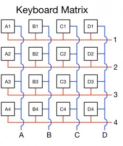
The red lines make up to row connections and the blue lines make up the column connections. The bumps in the column connections indicate that the wires don’t connect even though they overlap. In this case, there are 4 columns and 4 rows, and thus the micro controller would need 8 connections to read the key usage on the keyboard (8 connections for 16 switches).
Rows
In order to prevent ghosting in the keyboard (where the keyboard makes a mistake recognizing multiple key presses) diodes are added to each key switch. One thing I realized when looking at what other people had done when hand-wiring their keyboards, was that is was common to use the diodes themselves to connect switches in the rows. A diode lead is soldered directly to one of the switch contacts, and then the second lead is soldered to the second lead of the next diode. That might sound confusing, but it’s important. The connections between the diodes must be made such that the connections take place only between the second leads, creating a kind of rail that connects the leads, and creates a connection that cannot send electricity back up to the switches due to the diodes (which only allow electricity to flow in one direction). So one lead on the contact, and one on the next switches’ second lead. You continue in that pattern until you get to the end of the row.
The leads are only long enough to make the connection between regular size keys. If a larger key is used (like normally used for modifier keys like Shift, Tab, Backspace, etc. and the Spacebar) then the space is too long for the lead to reach across, and another solution is needed. In the case of the 2u modifiers (there are three in the Atomic layout) I simply soldered piece of diode leads that I had cut off previously (the part of the lead that attaches to the switch contact needs to be trimmed after it is soldered) to bridge the gap. For the spacebar, since it is significantly longer, I soldered a piece of wire to either side.
Here’s what the keyboard looks like with just the rows wired up (using the diodes):

There’s a difference between the rows and columns that is not clear from the diagram above. The columns are simply connected directly from contact to contact, since there are no diodes in the columns. This also means that there is no difference where you connect to the columns. The column is turned on, so to speak, by applying electricity to the whole column, so it that can be done anywhere. While the diagram shows the outgoing connections at the bottom of the diagram (similar to the row connections at the right of the diagram), the columns in reality end at the last switch in that column, and the connection can be made to one of the internal switches in the column (if that’s easier to fit the wiring), whereas the rows must be connected to at the end (after the last diode).
Columns
To wire the columns, I probably would have used solid-core wiring if I had had it, but I didn’t, so I used the bundle of wiring that Ortholinear sent with the plates, which is stranded wire. Since I wired the rows using the diode leads which are not insulated, the column wires must be insulated since they overlap the rows and would short if they were not insulated. After looking around at how other people had approached wiring up columns I came up with a technique that worked for me. What I did was strip the end of a segment of wire, which would be connected later to the bottom switch in the column. I then measured the distance to the next switch and made a cut in the insulation so I could pull the insulation up the wire a bit, creating a small gap in the insulation. It was important to measure to a couple of millimeters before the switch contact, and then pull the insulation so it created a gap a couple of millimeters past the contact, giving me enough space to solder the contact to the gap in the wire. After creating the gap, I would then measure to the next switch and repeat.
The reason I couldn’t measure all the distances at once was that I was pulling the insulation up the wire each time I created a gap, so any measurement marks I made earlier further up the wire would be moved. It was a bit time-consuming, but worked well. Once I had the wire for the column set up I pulled it under the row wires and positioned it next to each contact. I then soldered the bottom contact to the end of the wire and worked my way up the column until all the gaps were soldered to their proper contacts. The wire I had was color-coded, so I alternated colors across the columns, and made sure the colors followed the same order as the roll of wire, which came in handy later when connecting everything up (as you’ll see below). Here’s the keyboard with the columns wired:

You’ll note that the columns are not perfectly straight, because some keys span more than one column. When you have a wide key, you need to just pick one column to connect to that switch. To figure out which column would be assigned to which switch, I just decided on a rule that when there was a question I would connect to the left-most column the key spanned. On the bottom right of the keyboard above (actually the bottom left when the keyboard will be finished and flipped, but for this picture, it’s the bottom right) I just connected the bottom switches to the column they were closest to (they are off-center because they use larger keycaps). To guide me, I created a diagram like the above matrix diagram, but specific to this keyboard:

The reason it’s a good idea to make a diagram isn’t actually for wiring it, where a set of consistent rules should work well. The reason you need a diagram is that when you’re done and you want to program the controller, you’ll need to know how everything is hooked up. Having a diagram to look at can be simpler then referring to the actual hardware.
One thing to keep in mind. Technically the diagram above is backwards. We’re looking at the diagram the same way we’re looking at the back of the keyboard. The problem is that the software we’re going to load in the keyboard looks at the keyboard from the front. It also numbers the columns and rows starting from 0, so a more accurate diagram might be:

The firmware code actually uses hex numbering so there is no 10, 11, 12, 13 and 14, rather they are A, B, C, D, E and F. Since I’m using C and R to indicate Column and Row, however, I think it’s easier to label the switches using numbers.
Connecting the Rows and Columns to the Microcontroller
The next step is to connect everything we’ve done so far to the microcontroller, in this case a Teensy 2.0. Each column (15 of them) and each row (5 of them) need to be connected to the Teensy. Luckily, the Teensy has over 20 connections. The simplest thing to do is connect 10 wires to each side of the Teensy. In order to keep things organized, I decided to take the roll of wire I had, which was a strip 10 wires wide, consisting of insulation that came in ten sequential colors, and solder the wires to the rows and columns without disconnecting the wires completely. This allows me to end up with two strip of ten wires still connected at the ends, ready to connect to the Teensy. To pull this off, it required a bit of advanced planning. One thing I wanted to do, was re-use the same colors I had used for the columns, in the same order, so for each column, I was continuing the same color on its way to the Teensy. This would allow me to identify the wiring quickly when looking at the connections. For example, the first column is brown, and that will end up being the first connection on the Teensy. I’ll be able to visually see the connection of the brown wire to the first Teensy connection, and know for each connection exactly where it goes. There are 15 columns, but only 10 colors, but that’s okay because the next 5 columns will be connected on the other side of the Teensy with the rows. I was careful to run the wires underneath the existing rows and columns, and tried to keep the wires within the space between the keys whenever possible. This is what the wiring looked like when I finished:
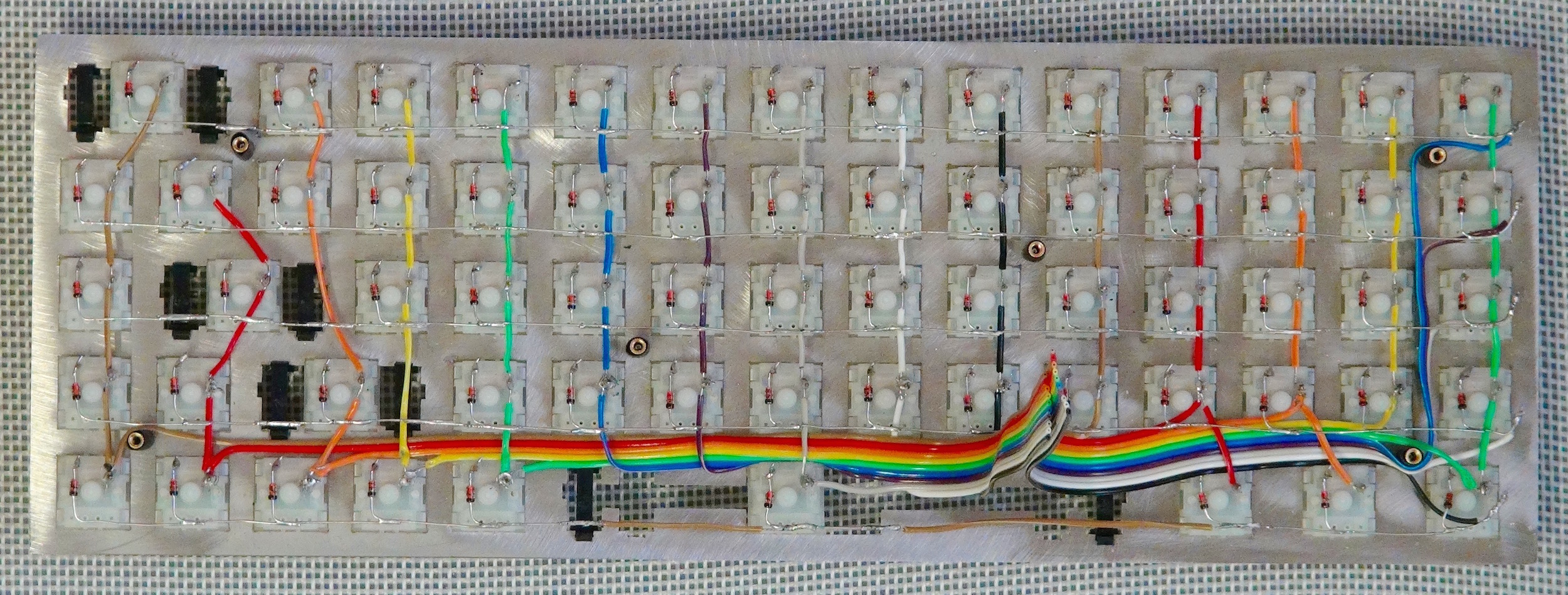
All the wires now run to the gap underneath the spacebar. That seems like the logical spot to place the microcontroller, as it’s the only spot without a switch in it. The right side of the spacebar switch is bigger than the left side (since the switch is not centered) so I put the wires there. In retrospect, it might have been easier to do the above if I had left the bottom row of switches disconnected from the columns, to make it easier to run the wires in the space between the switches. It wasn’t too bad, but it did require some delicate pulling of wires under the column wires which could have easily snapped in some cases.
Making the Teensy removable
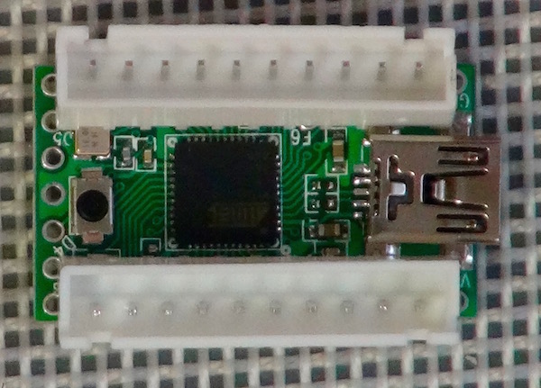
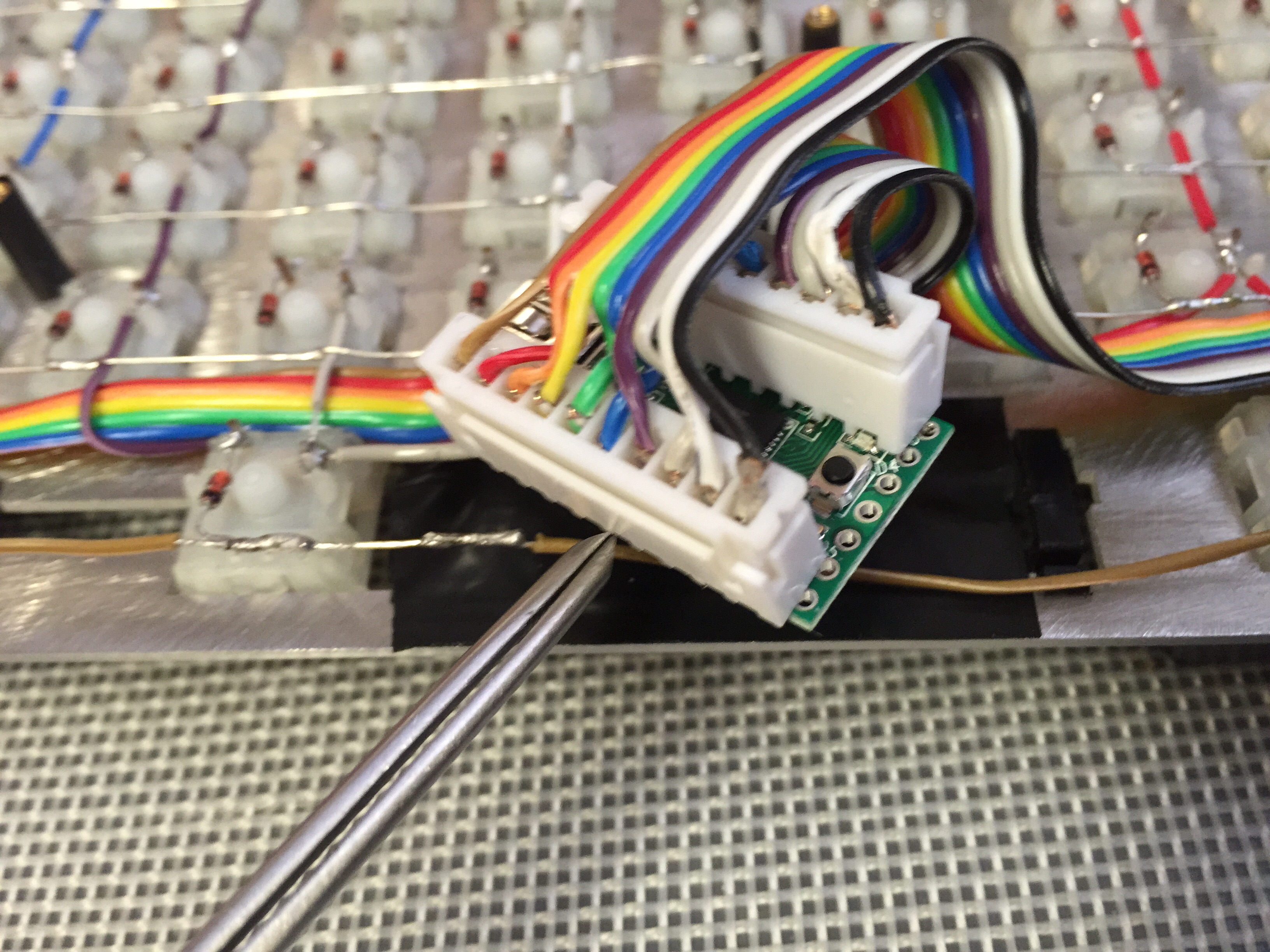
I decided the project wasn’t difficult enough, so I’d make it harder (that’s a joke). I wanted to be able to remove the Teensy from the keyboard at a later date without having to desolder it. Normally one would just solder the wires to the holes along the Teensy and be done with it. Making it removable required figuring out something clever to connect the wires to the Teensy without solder. What I came up with was to use dupont micro connectors. I ordered connectors that were 10 units wide. When I ordered them I wasn’t even sure they would line up properly with the holes on the Teensy, but luckily they did. The male side of the connector has pins on both the bottom and the top. I soldered the bottom pins into the Teensy, with one on either side of the Teensy.
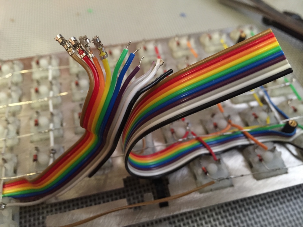
I then separate the ends of each wire coming from the rows and columns, and stripped the ends. The trick here is that the stripped section of wire has to be really short. One’s inclination is to give it a little extra space as you might do when soldering, but if you leave extra space here, the wire won’t fit properly in the dupont connector. Once I stripped all the wires, and practiced crimping the dupont connectors on extra wire I had, and then practiced inserting those connectors into the plastic female housing that held the ten connectors. This took a lot of practice, and I messed up a lot of connectors before getting a good feel for how it works. Even with all the practice, I ended up having to re-do two out of the twenty crimps that I did, but that’s not too bad.
Once I crimped all the connectors onto the wires, I inserted them into their housings and inserted the housing into their male counterparts on the Teensy. Along the way, I tried testing the connections using a multi-meter, just to make sure everything was working. This is what it looks like completed:
From a wiring point of view the keyboard is complete. There are three things left to do.
Close the case
First, we can close up the bottom. This keyboard came with a bottom plate with matching screw holes to the top plate. If you look at the photos above, there are brass spacers spread around the top plate in between the switches, six in total. I have black tubing around the brass spacers to prevent any wires from touching the metal. Those spacers have screw holes, so all I need to do is place the plate on top of those spacers and insert and tighten the screws.
Add keycaps
The second is to add keycaps to the switches (on the top of the keyboard):
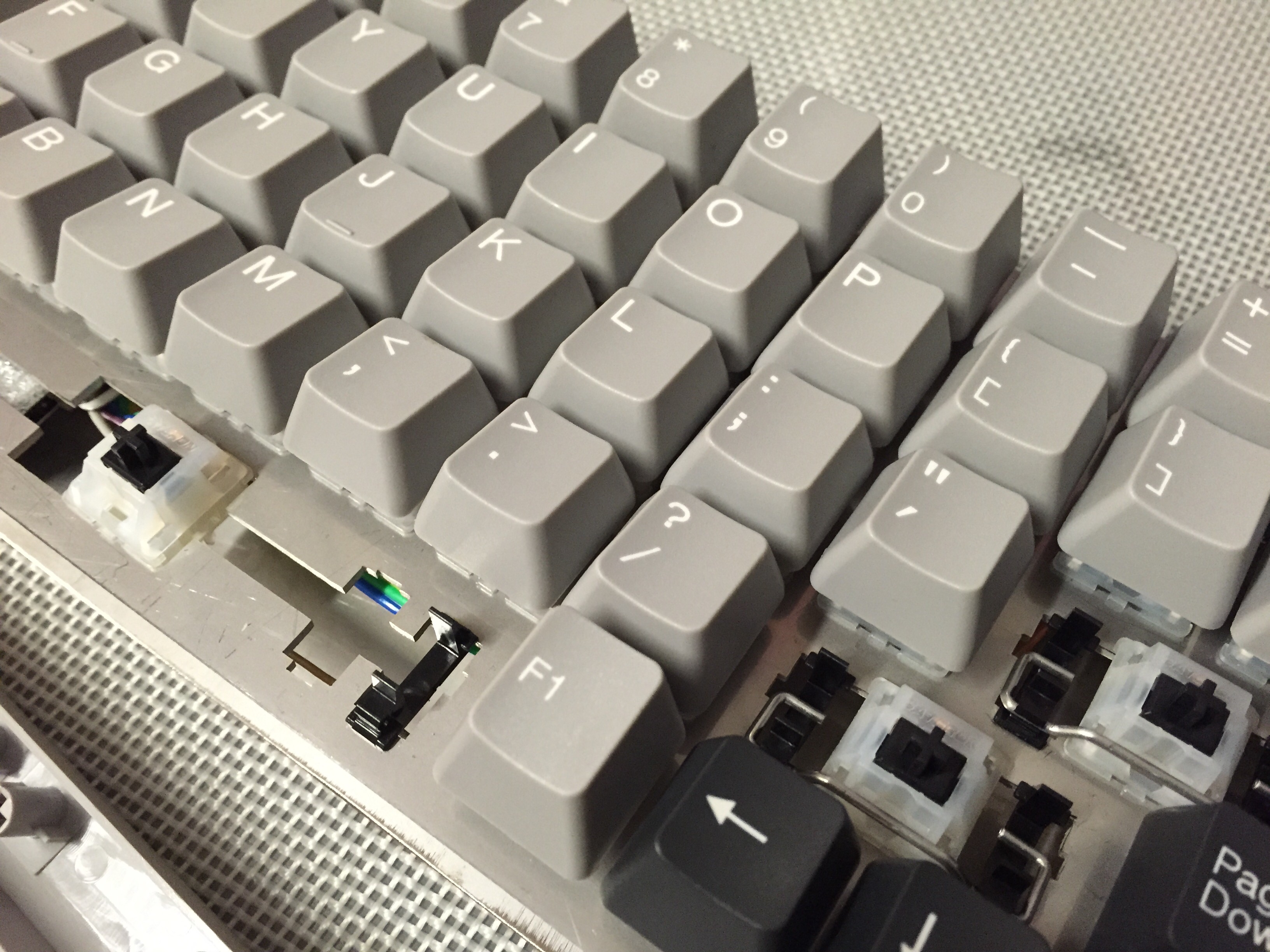
You’ll notice that a few switches don’t have keycaps. That’s because I was missing a stabilizer bar for the spacebar when I added the keycaps, and I didn’t have the right keys for the 2u keys which will be the right-shift and enter keys. As I’m writing this I’m expecting both the stabilizer bar for the spacebar, and some blank 2u keycaps to arrive in a couple of days.
Program the keyboard
The third thing that is needed is to program the firmware. Keyboard have their own software that tells the micro-controller (the Teensy) how to interpret keystrokes. Ortholinear recommends TMK firmware, and they’ve made their own branch of the code with some of the settings for their keyboard kits – in addition to the Atomic (matrix 60%), there is the Planck (matrix 40%), Neutrino (staggered 65%) and Quark (staggered 40%).
One can do a lot with the software in a keyboard, but there are a few basics that need to be done. First, you need to map the connections on the micro controller to specific columns and rows. If the firmware doesn’t know what each connection is connected to, it can’t determine which key was pressed. In addition, you need to tell the firmware which switch should trigger which keystroke. You also need to tell the firmware how many columns and rows are in the keyboard. Advanced firmwares like TMK support layering, which means you can add multiple ‘layers’ of keys, so one layer might be what you think is normal for a keyboard with numbers and letters, while a second layer might have function keys and number pad (for keyboards like this one that don’t have function keys or a number pad), and a third layer might have special application-specific macros for applications like Photoshop, or for specific games. To start out I used the layout that was set up as the default for the Atomic.
Basically, I followed the roadmap in matt3o’s guide How to build your very own keyboard firmware on deskthority, with a few changes since Ortholinear’s branch of TMK is already customized for their keyboards. At first, when I tried to compile I ran into a string of error messages, but after asking Jack Humbert (aka Ortholinear) his thoughts on what was going on, he pointed out a single missing # in my code was causing it to fail. Adding in the # and everything worked.
Well, sort of. When I originally complied the firmware and got the keyboard working, the keymap seemed not to be exactly what I thought it would be. I don’t need to go into all the gritty details here, but let’s just point out that programming a keyboard from scratch is not something most people would ever want to do. Not only do you need to check the code, but you need to check the hardware to make sure your problems are not due to a soldering mistake. It’s not fun.
Finishing the Keyboard
In order to finish the keyboard, I needed two things. First, I needed to install the missing keycaps. All three missing keycaps used stabilizers, as all keycaps at least 2 units wide (i.e. twice the width of a standard key) need stabilizers in order to allow the key to press evenly across the entire key. After I received a 6.25u stabilizer bar for the spacebar, I installed that and the spacebar. After receiving 2u keycaps, I installed those on the stabilizers as well. Now all the keycaps were installed.
Second, I needed to make the USB port on the Teensy accessible. This is where some advanced planning would have helped a bit, but truthfully I started building the keyboard without the part I needed, so it wouldn’t have helped unless I had decided not to build the keyboard. The part I needed was a short USB extension cord so I could connect it to the USB port on the Teensy and run it in between the key switches and out the top of the keyboard. The advanced planning part would have been to run the extension cord in between the switches before all the soldering, so it would fit underneath the connections and stay in place. The problem I had after the fact was that I could not fit the extension cord underneath the connections without stripping the wire almost completely. That meant the plastic insulation was gone, and I would need to insulate the wire after getting it into place. I still haven’t found a great solution to this problem, although for the time being the USB extension cord is wrapped in electrical tape.
Great work with the connectors to make the Teensy removable, thanks for sharing your build process, very helpful.